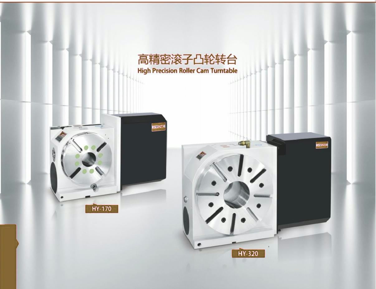
4th Axis Rotary Table
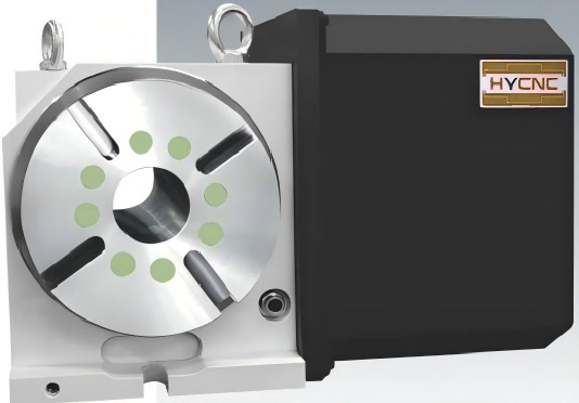
HY170 CNC 4th Axis Rotary Table
The most compact model in the range, positioned for smaller workpieces and machines where table space is limited.
Roller Cam Rotary Tables for CNC Machining Centers
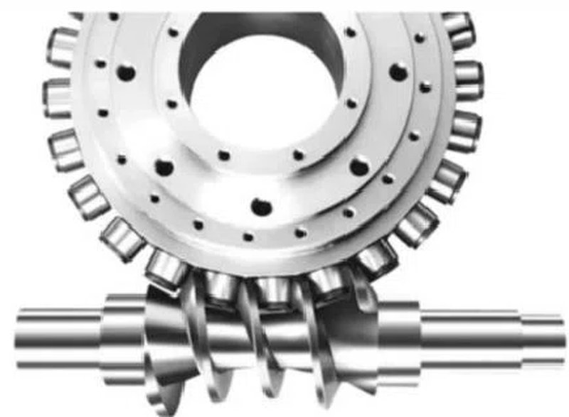
Four core 4th axis rotary table models — HY170, HY200, HY250 and HY320 — built on the same roller cam drive platform and supplied with matching tailstock, chuck and accessory configurations.
All four models are core products of the 4th axis range. Each has its own table size, workpiece envelope and configuration options — full verified specifications are published per model page.
The most compact model in the range, positioned for smaller workpieces and machines where table space is limited.
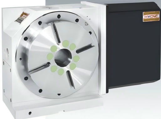
A mid-range model for general multi-side and indexed machining of shaft, flange and gear type parts.
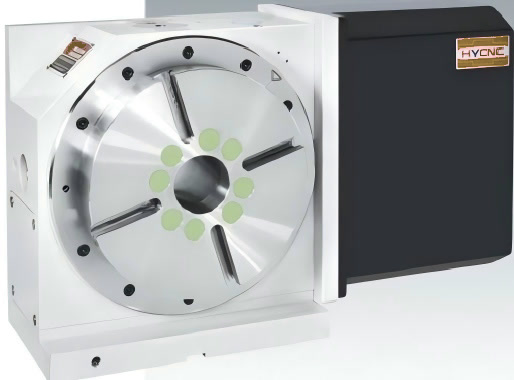
A larger model for workpieces that need more table area and greater distance from the machine spindle.
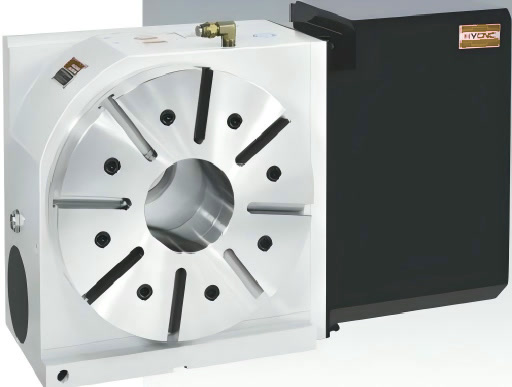
The largest model in the range, positioned for larger rotary machining applications on machining centers.
Positioning descriptions above refer to each model's place within the range. Final model selection always depends on verified specifications, machine data and workpiece requirements — please confirm with our engineering team.
Compare the four models across the criteria that matter for machine integration. Verified values are published as soon as the data is released by our engineering team; unverified fields remain marked for completion.
| Criteria | HY170 | HY200 | HY250 | HY320 |
|---|---|---|---|---|
| Dimensions | ||||
| Table diameter | 170 mm | 200 mm | 250 mm | 320 mm |
| Center height | 135 mm | 160 mm | 160 mm | 210 mm |
| Overall dimensions | On request | On request | On request | On request |
| Weight | 51 kg | 80 kg | 85 kg | 220 kg |
| Workpiece capability | ||||
| Workpiece size | On request | On request | On request | On request |
| Workpiece weight | 80 kg (vertical) / 160 kg (with tailstock) | 95 kg (vertical) / 210 kg (with tailstock) | 120 kg (vertical) / 240 kg (with tailstock) | 210 kg (vertical) / 420 kg (with tailstock) |
| Machine integration | ||||
| Machine table space required | On request | On request | On request | On request |
| Installation requirements | On request | On request | On request | On request |
| CNC compatibility | Depends on machine & control — contact us | Depends on machine & control — contact us | Depends on machine & control — contact us | Depends on machine & control — contact us |
| Range positioning | ||||
| Position within range | Most compact model | Mid-range model | Larger model | Largest model in the range |
| Application focus | Smaller workpieces, limited table space | General multi-side & indexed machining | Larger workpieces, longer reach | Larger rotary machining applications |
| Available configurations | Chuck / tailstock / accessory options to be confirmed | Chuck / tailstock / accessory options to be confirmed | Chuck / tailstock / accessory options to be confirmed | Chuck / tailstock / accessory options to be confirmed |
Values marked “On request” depend on the motor, encoder and workholding option selected. Range positioning is descriptive only and is not a specification. CNC compatibility depends on the machine model and control configuration. Please contact us for confirmation.
Five steps used by our sales engineers when matching a rotary table to a machine and a part. Each step is also explained in the technical guide.
Identify the machining center, available table area and how the rotary table will be mounted.
Define workpiece dimensions, weight and how the part will be held during machining.
Match table diameter and center height so the workpiece clears the spindle through the full rotation.
Decide between chuck, fixture plate or faceplate, and whether a tailstock is required for long parts.
Provide the controller model, motor and drive configuration so we can confirm the interface.
Send your machine and workpiece details — we confirm the final configuration before quotation.
All four 4th axis models are built around the same roller cam drive platform. Backlash and accuracy figures are published only from verified test data supplied by our engineering team.
Rotary motion is transmitted through rolling elements in continuous engagement with the cam profile.
A compact drive structure designed to support machining loads on the rotary axis.
Indexed positioning for multi-side machining operations. Accuracy data published after verification.
Rolling contact in the drive train is designed to support durable operation in production environments.
Rotary table integration depends on factors on both the machine side and the rotary table side.
CNC compatibility depends on the machine model and control configuration. Please contact us for confirmation.
Verified compatibility data — including specific CNC controllers — will be published only after confirmation by our engineering team.A 4th axis installation usually combines the rotary table with workholding and workpiece support. Matching options are confirmed per model.
Application pages explain the machining problem, how a rotary table helps and a suitable configuration. No cutting data or customer cases are published without verified information.
Tell us your machine type and the parts you need to machine. We will confirm the suitable 4th axis model and configuration.